
DIRECT SHAFT FEEDBACK / ENGINEERING GUIDE
The shaft turns.
The housing stays still.
A hollow shaft encoder measures angular position or speed while a clamping collar couples its rotating element to the machine shaft. A flexible stator tether restrains the housing within its specified movement limits.
01 / CHOOSE THE MECHANICAL INTERFACE
One shaft. Three ways to read it.
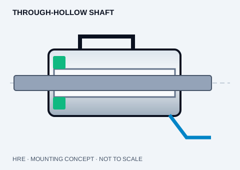
Through-hollow
A continuous bore lets the shaft pass through the encoder. Check clamp access and shaft clearance.
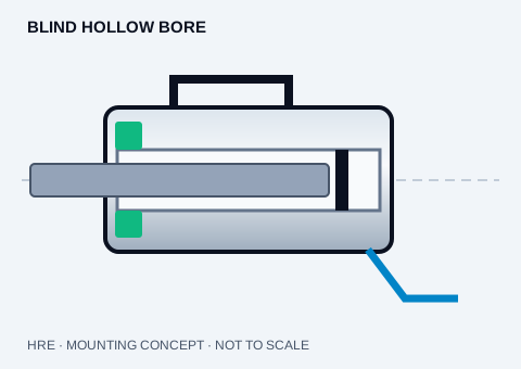
Blind hollow bore
A closed bore fits the shaft end. Check insertion depth and avoid bottoming out the shaft.
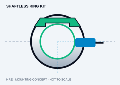
Shaftless ring kit
A ring and readhead use the machine bearing. Check sensing gap, runout and calibration.
Original engineering concepts. Not to scale; final housing, ring and mounting dimensions require an approved drawing.
Incremental pulses or absolute position?
An incremental hollow shaft encoder produces repeating pulses, often A/B quadrature and an index Z. The controller counts edges to determine motion. Absolute encoders transmit a position code; multiturn feedback additionally tracks rotations using a configuration-specific retention method.
For an encoder rated in cycles per revolution, channel frequency is PPR × RPM / 60. At 2048 PPR and 3000 RPM, that is 102.4 kHz per channel. A controller using ×4 quadrature decoding processes 409.6 kcounts/s. Check the supplier’s PPR/CPR convention and the controller input limit.
Support the tether without forcing the shaft.
- Isolate machine power. Follow the approved model-specific assembly and machine safety procedure.
- Measure shaft diameter, tolerance, runout and engagement length. Check clearance and clamp access.
- Use only an approved sleeve and clamping arrangement. A sleeve adapts a smaller shaft to a larger bore; it cannot make a larger shaft fit a smaller bore.
- Install the stator tether without preload beyond its limits. Use the configuration drawing for fastening sequence and torque.
- Verify connector pinout, shielding, supply and output before energizing. Confirm direction, zero/index and controller scaling at low speed.
PEEK insulation needs a complete current-path review.
An insulating bore sleeve can interrupt conduction from shaft to encoder. Metal tethers, fasteners, connector shields or other contacts can bypass that insulation. Check sleeve wall thickness, clamp retention, creep and environmental suitability, then verify the complete installed isolation path.
Ring encoders transfer mounting precision to the machine.
A shaftless encoder separates the ring and readhead. Your bearing controls their relative motion. Gap, concentricity, tilt and thermal movement influence error; digital bit count alone is not an accuracy specification.
PRIMARY REFERENCE MATERIAL
SICK DBS60 mounting instructions ↗ · Dynapar HS35 datasheet ↗ · RLS ring encoder catalogue ↗
Manufacturer documents describe the original products. HRE configuration and interchangeability require a separate engineering review.
ENGINEERING HANDOFF / Mounting & working principle review
Start with your shaft.
We’ll review the fit.
Send the exact bore, signal and application. Request a configuration review, quotation and matching STEP drawing in one inquiry.
[email protected] ↗Drawings and detailed specifications are confirmed for the selected configuration. Please include your original full model code for a replacement review.